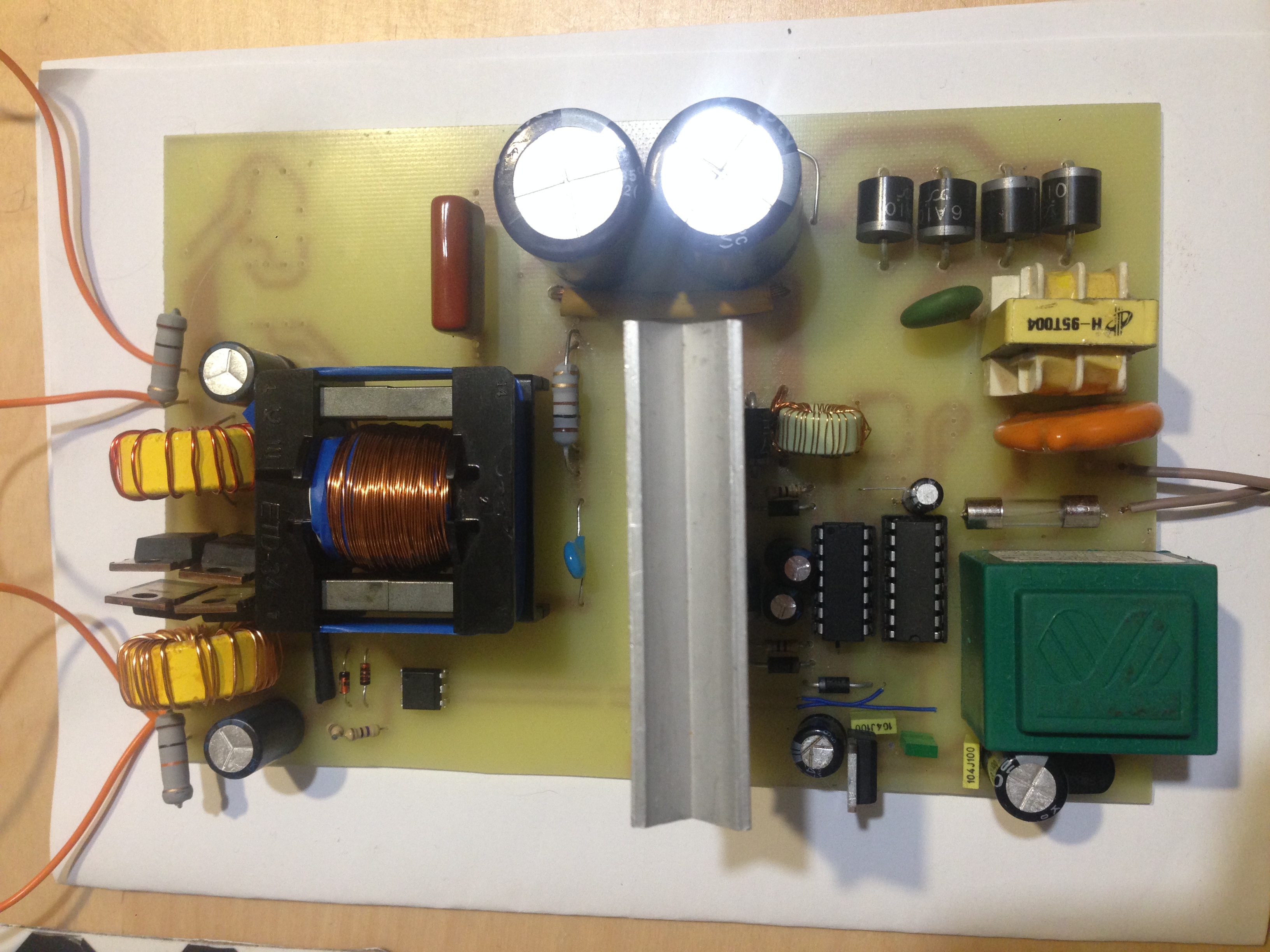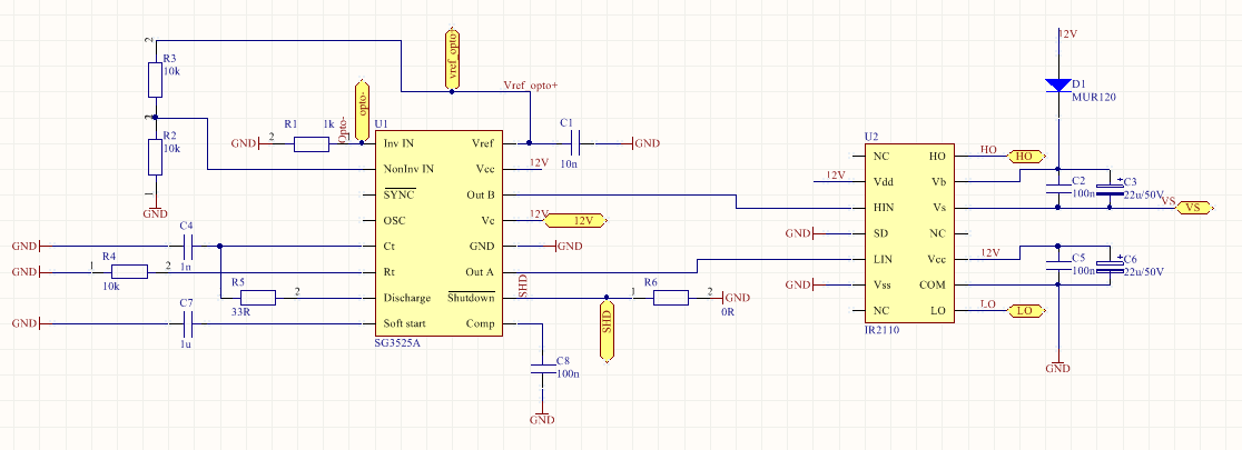
While the current control method uses Output current from output inductor to compare it with the reference value and to set the duty cycle of PWM. In return to control the output voltage of SMPS. The voltage control method used a feedback voltage by comparing it with a reference value to set a duty cycle of PWM. There are two types of PWM controller integrated circuits: I will discuss these things in detail later in this article. These PWM controllers ICs you can use very easily in your SMPS projects by connecting some external circuitry with them according to the selection of frequency. There are many PWM ( Pulse width modulation ) controller integrated circuits available in the market just like SG3525. Therefore, Pulse width modulation is a preferred technique for control circuits of switch-mode power supplies. Pulse width modulation also resolves the issues which occur in Pulse frequency modulation. The width of the pulse or on time increase with the increase in load. On the other hand in Pulse width modulation technique frequency remains constant but the width of pulse changes with the change in load. But the Pulse frequency modulation technique causes some issues in switch-mode power supplies. In Pulse frequency modulation technique on time of pulse remains constant but the frequency increases with the increase in load. A comparison is made with the reference and the output of the opamp will feed the opto directly.Control-Integrated circuit for SMPS SG3525: Pulse frequency modulation and pulse width modulation are two types of techniques used in control integrated circuits for switch-mode power supplies. You can insert a voltage divider network with the output feeding an opamp input, the TL431 will be used as a reference for the opamp other input. One other thing that I noticed was when giving the smps an continuous load at full power the output inductor started heating a bit and as the core changes the value due to heat the output voltage did drift a little.

One other thing that I added was a 200nF cap across the zener and it helped a lot with a stable regulation. I suggest you insert a preset at first until you get the right resistor value than you can put a fixed one when the value is known.

In your case I guess you have to go somewhat lower with the resistor. and feeding the reference, The circuit values shown are for 50v I needed 60v the resistor on the circuit shows a 33K resistor in my case I ended up using a 47K instead and got a 60v output.

What I found out was that the resistor before the zener has to be tailored in such a way to the point where the zener starts to conduct when it hits the target voltage. Well when I first tried this feedback circuit I asked myself the same question.


 0 kommentar(er)
